Monolithic 3D Inc., the Next Generation 3D-IC Company
  • Home
  • Technology
    • Technology
    • Papers, Presentations and Patents
    • Overview >
      • Background
      • Why Monolithic 3D?
      • Paths to Monolithic 3D
      • Applications
    • Ion-Cut: The Building Block
    • Monolithic 3D Logic >
      • RCAT
      • HKMG
      • Laser Annealing
      • RCJLT
      • 3D Embedded RAM
      • 3D Gate Array
      • FPGA
      • Ultra Large Integration - Redundancy and Repair
    • Monolithic 3D Memory >
      • 3D DRAM
      • 3D Resistive Memories
      • 3D Flash
    • Monolithic 3D Electro-Optics >
      • 3D Image Sensors
      • 3D Micro-Displays
  • 3D-IC Edge
    • 3D-IC Edge
  • News & Events
    • News & Events
    • S3S15 Game Change 2.0 Video/P
    • Webcast
    • Webinar
    • Press Releases
    • In the News
    • Upcoming Events
  • About Us
    • About Us
    • History
    • Team
    • Careers
    • Contact Us
  • Blog
  • Simulators


Local Interconnect Model

IntSim v2.0 has two metal levels for each device layer to route local signal, power and clock interconnect networks. These metal levels are also designed to remove heat from transistors in stacked device layers. Local interconnect pitch is selected as 2F, where F is the minimum feature size. Length of the longest signal wire routed in local interconnect levels is obtained from the equations shown in Fig. M11. Power wire efficiency is obtained from the local power grid model derived in [26] and also from considerations shown in the thermal models page. Via blockage to higher metal levels and via blockage due to repeaters are modeled using equations derived in [27].  

Picture
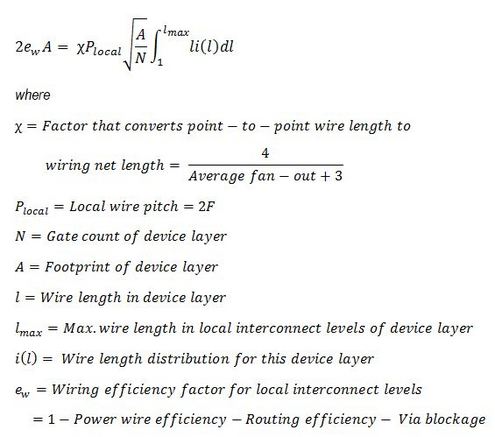
Fig. M11: Local interconnect models.

© Copyright MonolithIC 3D Inc. , the Next-Generation 3D-IC Company, 2012 - All Rights Reserved, Patents Pending